1. Air Law and Air Traffic Control Procedures
1.1 Canadian Domestic Airspace Structure (NDA, SDA, SPR, ASR, Class A–G)
- Canadian Domestic Airspace Structure:
- SDA uses magnetic tracks.
- NDA uses true tracks.
- 🧠 SDA = South = Magnetic.
- 🧠 NDA = North = True.
- Reference table included here: Class A–G airspace comparison.
| Class | Altitudes | VFR Entry | IFR Entry | XPDR | Radio (VFR) | Radar | Use | ATC Sep | Flight Plan |
| Class A | FL180 and above | N/A – IFR only | Clearance required | Mode C required | N/A | Radar | High-level IFR enroute | IFR–IFR | IFR required |
| Class B | 12,500'–17,999' ASL in some TCAs | ATC clearance required | Clearance required | Mode C required | Yes | Radar | Busy IFR corridors | IFR–IFR and IFR–VFR | IFR required; VFR often required for crossing |
| Class C | Various TCAs and busy airports | ATC clearance required | Clearance required | Mode C required | Yes | Radar | Major airport terminal areas | IFR–IFR and IFR–VFR | IFR and VFR required by area |
| Class D | Control zones, e.g., CYKF CZ | Two-way radio contact required | Clearance required | Often required | Yes | Radar or non-radar | Medium airports like CYKF | IFR–IFR; VFR receives traffic information | IFR required; VFR not always |
| Class E | Controlled low-level routes, airways, above Class G | No clearance required | Clearance required | Not typically required | No | May be radar or procedural | Low-level airways and transition areas | IFR–IFR; VFR on request | IFR required; VFR optional |
| Class F | Advisory/restricted areas | May require prior permission or be restricted | Depends on restrictions | Depends on area | Sometimes | Typically non-radar | Military or special use | May provide separation within restrictions | |
| Class G | Uncontrolled airspace, surface up to base of Class E | No clearance required | ATC clearance recommended but not required | Not required | No | Non-radar | Remote/uncontrolled areas and training zones | None | IFR required; VFR optional if >25 NM |
1.2 IFR Flight Rules in Controlled and Uncontrolled Airspace
- Must file an IFR flight plan and receive clearance before entering controlled airspace.
- Alternate Requirements: When weather at the destination is below 800-2 or 600-2 (precision/non-precision).
- IFR is permitted in Class G, but pilots are responsible for separation and obstacle clearance
| Class A | IFR only (FL180 -FL600) |
| Class B |
|
| Class C | Controlled, IFR/VFR, Requires ATC clearance |
| Class D | IFR & VFR with ATC clearance, ATC separation for IFR only |
| Class E |
|
| Class F | Advisory/Restricted |
| Class G |
|
1.3 ATC Clearances: Flight Plan Filing, Amendments, Holding Instructions
- Clearance limit = the furthest point ATC has cleared you to proceed.
- If you reach a clearance limit and there is a published hold, hold as published.
- If you reach a clearance limit and there is no published hold, hold in a standard pattern on the inbound track to the clearance limit and request further clearance.
- Do not continue past the clearance limit without further ATC clearance.
- If unable to comply with a clearance or holding instruction, advise ATC as early as possible.
- No landing clearance on final = do not land; go around or fly the missed approach as required.
- 🧠 Published hold exists → hold as published.
- 🧠 No published hold → standard hold on the inbound track.
- 🧠 Can’t comply? Don’t improvise — tell ATC early.
Part IV - Recency, Validity and Privilege Requirements (401.05)
- Recency Requirment to act as PLC/SIC (Co-pilot):
- Have flown as PIC/SIC in the last 5 years or, Completed a flight review + written exam.
- For IFR use, within:
- 6 months: 6 hours IFR + 6 approaches
- 24 months: IPC, IFR flight test, or PPC with IFR component
Part IV - Instrument Rating Groups – Privileges
| Group 1 | Fly all multi-engine and single-engine aircraft under IFR |
| Group 2 | Fly multi-engine centreline thrust aircraft only under IFR |
| Group 3 | Fly single-engine aircraft only under IFR |
| Group 4 | Fly helicopters only under IFR |
Part IV - Air Traffic
- Compliance with ATC Clearances:
- You must follow ATC clearance unless:
- Amended by ATC
- Emergency
- Unsafe to comply
Part IV - Altitude Compliance
- Must fly at or above:
- MEA - Ensures obstacle clearance + NAVAID reception along the entire route
- MOCA - Provides obstacle clearance but guarantees navigation signal coverage only within 22 NM of a VOR.
- MOA - Minimum Obstruction Clearance Altitude
- 1,000’ AGL (non-mountainous), 2,000’ AGL (mountainous) if no published minimums
- Must not operate under VFR:
- Provides safe vertical clearance from obstructions
- Less than 1,000 ft AGL over built-up areas
- Unless in accordance with exceptions (e.g., takeoff/landing/emergency).
- IFR Cruising Direction & Altitudes:
- 000°–179° = Odd thousands (FL190, FL210...)
- 180°–359° = Even thousands (FL200, FL220...)
Part IV - IFR Position Reports
- Position Reports – IFR Controlled Airspace
- Must report when:
- Entering / leaving holds
- Reaching/Leaving clearance limit
- Missed approach
- VOR changeover point (when required)
- Sample Position
- Aircraft Identification – (e.g., Piper Arrow GVBV)
- Position – Name of the fix or waypoint (e.g., BOOTH Intersection)
- Time Over the Fix – (e.g., 1523 Zulu)
- Altitude – Current cruising altitude (e.g., 8000 feet)
- Estimated Time to Next Fix – (e.g., ETA JAKKU at 1545 Zulu)
- Next Fix After That – (e.g., Next fix after JAKKU is ALDER)
Part IV - Communications Failure (602.36)
- If two-way radio communications fail in IFR, squawk 7600.
- Route to fly is determined by AVEF priority.
- AVEF = Assigned, Vectored, Expected, Filed.
- Maintain the appropriate altitude/route and continue according to the applicable IFR communications-failure procedure.
- AVEF route-order priority: Assigned, Vectored, Expected, Filed.
- Assigned = last ATC-assigned route.
- Vectored = route to fix/vector ATC was giving before failure.
- Expected = route you were told to expect in a clearance.
- Filed = route originally filed in your flight plan.
- 🧠 AVEF = Assigned, Vectored, Expected, Filed.
Part VI - General Operating and Flight Rules
Pre-flight Information, Fuel, alternative, weather minima, Instrument Approaches, Landing Minima, Two-way Radio, Take-off Minima
- Unauthorized Take-offs and Landings
- No person shall take off or land an aircraft in a prohibited or restricted area unless authorized.
- Right of Way – Converging Aircraft
- Aircraft on the right has the right of way (except head-on or overtaking situations).
Oxygen Requirements
- IFR: Oxygen must be available when:
- Cabin pressure altitude > 10,000 ft for more than 30 minutes
- Always if > 13,000 ft.
- Oxygen Requirements – Crew/Passengers
- If cabin pressure alt >10,000 ft (more than 30 min) or >13,000 ft anytime:
- Flight crew must use oxygen
- Must carry sufficient oxygen for all crew and 10% of passengers (for minimum 30 minutes)
Operational and Emergency Equipment Requirements
Flight Preparation, Flight Plans and Flight Itineraries
Operations at or in the Vicinity of an Aerodrome
Instrument Flight Rules
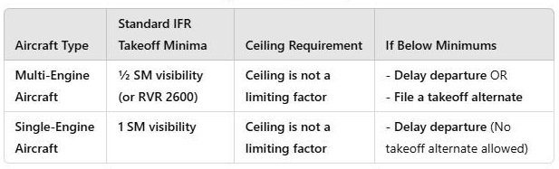
602.126 Take-off Minima
- Takeoff in lower visibility requires specific CAP takeoff minima authorization or opertor approval
- Take off Minima - Canada
| Aircraft | Standard IFR Take of Minimum | Ceiling Requirement | IF Below Minimums |
| Multi-Engine Aircraft | ½SM visibility (or RVR 2600) | Ceiling is not a limiting factor | Delay departure OR Filea takeoff alternative |
Radiocommunications - IFR Departure Clearance Readback
- Clearance Limit – Destination (e.g., Cleared to Calgary)
- Departure Procedure (SID if applicable) – (e.g., Vancouver 4 departure)
- Route of Flight – (e.g., Flight planned route)
- Initial Altitude & Expectation – (e.g., Maintain 5000, expect FL190 in ten)
- Transponder Code – (e.g., Squawk 4321)
Aircraft Requirements - 605.18,605.30,401.47,401.48
- Power-driven Aircraft – IFR, De-Icing or Anti Icing,
| IFR Equipment – Power-driven Aircraft To fly IFR, aircraft must have: |
|
| De-Icing/Anti-Icing Equipment | Aircraft must not take off with frost/ice/snow on wings, props, or sensors unless certified for it (de-icing/anti-icing systems) |
| Instrument Rating |
|
| Instrument Rating – Validity |
|
Air Traffic Services
1. Low level controlled airspace / types / dimensions / flight rules
Air Traffic Services
2. Classification of airspace
Air Traffic Services
3. Special use airspace
Route and flight Planning
6.Fuel requirements – aeroplanes, helicopters
- Fly to the destination aerodrome;
- Execute an approach and a missed approach;
- Fly to and land at the alternate aerodrome;
- Then fly for an additional 45 minutes at normal cruising speed.
Route and flight Planning
7. Weather requirements – take-off, landing, alternate
- Ensure that the destination's forecasted weather from one hour before to one hour after your ETA meets the required minima: a ceiling of at least 1,000 feet above the FAF altitude and visibility of at least 3 statute miles
Departure Procedures
- Single-engine aircraft require 1 SM visibility for IFR takeoff (unless otherwise published).
- Multi-engine aircraft may take off with ½ SM visibility.
- Takeoff alternates are required when the departure airport is below landing minima, not just because visibility is low.
- Takeoff Minima: Based on aircraft category; RVR 1200 or greater required in most cases, and check the airport’s published IFR takeoff minima in the CAP GEN and departure charts.
En Route Procedures
Intercept
- Use a 30°-45° intercept angle when joining a VOR radial for efficient tracking.
- CDI full deflection means you are far off-course—use an intercept heading.
- Inbound radial means flying opposite to the radial’s bearing (270° radial = 090° inbound).
- Avoid excessive corrections—small adjustments help maintain course accuracy.
En Route Procedures
1. Position reports
- Position Reports: Required in non-radar environments and for altitude changes.
En Route Procedures
4. Altitude Limitations – MEA, MOCA, MRA, GASA
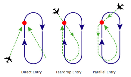
Holding Procedures
- Holding entries: Direct, Parallel, Teardrop.
- Standard hold = right turns.
- Non-standard hold = left turns.
- Fix is the centre of the holding picture.
- Radial = FROM the station; inbound course is normally the reciprocal.
- Direct entry = cross the fix and join the racetrack right away.
- First crossing = entering; after completing the entry and crossing the fix again = established.
- Report established after completing the entry and joining the normal racetrack, not simply at the first fix crossing.
- At or below 14,000 ft ASL → 1 minute outbound/inbound timing target.
- Above 14,000 ft ASL → 1.5 minutes outbound/inbound timing target.
- Start outbound timing abeam the fix or when established on the outbound heading, whichever occurs later.
- Abeam = the fix is beside you, about 90° off the wing.
- At or below 6,000 ft ASL → maximum holding speed 200 KIAS.
- 6,001 ft to 14,000 ft ASL → maximum holding speed 230 KIAS.
- Above 14,000 ft ASL → maximum holding speed 265 KIAS.
- If a chart publishes a lower holding speed, the published chart restriction wins.
- DME hold = use distances, not timing.
- Hold between 10 DME and 15 DME → leg length is 5 NM.
- In a 10–15 DME hold: turn outbound at 10 DME and turn inbound at 15 DME.
- Inbound too long → shorten the next outbound leg.
- Inbound too short → lengthen the next outbound leg.
- Outbound wind correction = about 3 × inbound correction, opposite direction.
- Inbound too long → outbound shorter; inbound too short → outbound longer.
- Inbound correction × 3, opposite side outbound.
- 🧠 Standard = right; non-standard = left.
- 🧠 6 / 14 / above = 200 / 230 / 265.
- 🧠 Chart beats the general holding-speed table.
- 🧠 Inbound too long → outbound shorter.
- 🧠 Inbound too short → outbound longer.
- 🧠 Inbound correction × 3, opposite side outbound.
- Example: Hold east on the 090 radial → holding area east of VOR, outbound 090°, inbound 270°.
- Example: Hold north on the 360 radial → holding area north of VOR, outbound 360°, inbound 180°.
- Wind direction aid: If you correct right, the wind is coming from your left.
- 🧠 Inbound too long → outbound shorter; inbound too short → outbound longer.
- Reference table included here: holding speed/time.
| Altitude (MSL) | Max Holding Speed (KIAS) | Standard Holding Time |
| Up to 6,000 ft | 200 | 1 min |
| 6,001–14,000 ft | 230 | 1 min |
| Above 14,000 ft | 265 | 1.5 min |
Approach Categories
Approach categories are based on aircraft approach speed and are used to define protected airspace, circling radii, and approach minima.
- Approach categories are based on VREF or 1.3 × VS0, whichever is higher.
- Used for circling minimums.
- Used for protected airspace radii.
- Used for charted approach lines and different minima by category.
- 🧠 Category speed drives protected airspace and minima.
- 🧠 Faster aircraft = larger protected area / higher category.
- Reference table included here: aircraft approach categories A–E.
| Category | Approach Speed (VREF or 1.3 × VS0) |
| A | < 91 knots |
| B | 91–120 knots |
| C | 121–140 knots |
| D | 141–165 knots |
| E | > 165 knots (military only) |
An LPV (Localizer Performance with Vertical guidance) approach:
- Is an RNAV (GNSS) approach
- Uses WAAS (Wide Area Augmentation System)
- Provides both lateral and vertical guidance
- Uses a DA (Decision Altitude), like an ILS
- But is not classified as a precision approach under ICAO
Missed Approach
- DA = Decision Altitude: decide immediately, land or missed.
- MDA = Minimum Descent Altitude: maintain MDA until the MAP unless visual reference is established.
- Non-precision approach uses MDA and MAP.
- Precision/APV approach uses DA.
- At MAP on a non-precision approach, if runway environment is not in sight → execute missed approach.
- At DA on ILS/LPV/LNAV/VNAV, if runway environment is not in sight → execute missed approach immediately.
- Do not descend below DA/MDA unless the required visual reference is established and the aircraft is in a normal position to land.
- Do not level off at DA; DA is a decision point, not a level-off altitude.
- 🧠 DA = Decide Now.
- 🧠 MDA = Maintain Until MAP.
- 🧠 No runway at MAP = go missed.
- 🧠 DA/MDA tells you if you may continue to land.
- 🧠 LP/LNAV use MDA; LNAV/VNAV/LPV use DA.
- 🧠 DA = Decide Now; MDA = Maintain Until MAP.
- Reference table included here: MDA vs DA comparison.
| Feature | MDA (Non-Precision) | DA (Precision/APV) |
| Type of Approach | VOR, NDB, LNAV, LOC | ILS, RNAV LPV / LNAV/VNAV |
| Pilot Action | Can level off at MDA and continue to MAP | Must go missed if no visual reference at DA |
| Missed Approach Decision Point | At MAP | At DA |
| Descent Allowed Below Minimum? | ❌ No, unless required visual references are obtained | ❌ No, execute missed approach immediately if no visual reference |
Approach Ban
- Approach ban = gate before final.
- Approach ban is checked before continuing past the FAF.
- Approach ban is based on reported visibility/RVR, not ceiling.
- ATC approach clearance does not cancel the approach ban.
- RVR = Runway Visual Range, the distance a pilot can see along the runway.
- RVR 2600 is commonly treated as about 1/2 SM.
- You may continue if RVR improves above minimums before reaching the FAF.
- If RVR drops after passing the FAF, continue only if legally allowed and required visual reference exists at DA/MDA.
- Circling approach requires maintaining required visual reference with the airport/runway environment.
- DA/MDA is the landing decision point after the approach-ban gate has been satisfied.
- 🧠 Approach ban = gate before final.
- 🧠 Approach ban tells you if you may continue inbound.
- 🧠 DA/MDA = landing decision.
- 🧠 DA/MDA tells you if you may continue to land.
- 🧠 RVR = runway seeing distance.
- 🧠 Approach ban = gate before final; DA/MDA = landing decision.
CAP GEN Definitions
Emergencies
1.8 Minimum IFR Altitudes (MOCA, MEA, MIA, MSA, OROCA)
- MEA = Minimum Enroute Altitude; published on chart; route-specific; guarantees obstacle clearance and navigation signal coverage along the entire route segment.
- MIA = Minimum IFR Altitude; lowest ATC-cleared IFR altitude in an area; obstacle clearance is provided and nav signal coverage is available if needed for that clearance.
- MOCA = Minimum Obstacle Clearance Altitude; published on chart, often with an asterisk; route-specific obstacle clearance with nav signal coverage only within 22 NM of the navaid.
- MSA = Minimum Sector Altitude; quick reference for safe altitudes near an airport fix; normally provides 1,000 ft obstacle clearance within 25 NM, but does not guarantee nav or communication coverage.
- OROCA = Off-Route Obstacle Clearance Altitude; general obstacle clearance off airways, with no navigation signal guarantee.
- Non-mountainous IFR minimum obstacle clearance: 1,000 ft above the highest obstacle within 5 NM of the route.
- Mountainous regions 1, 2, 3, or 4 IFR minimum obstacle clearance: 2,000 ft above the highest obstacle within 5 NM of the route.
- For off-route/non-published minimums, signal coverage is not guaranteed unless an MEA is published.
- MEA provides route-specific navigation signal coverage; MSA and OROCA do not.
- 🧠 MEA = route + signal.
- 🧠 MIA = ATC’s lowest IFR altitude for an area.
- 🧠 MOCA = obstacle first, signal limited.
- 🧠 MSA = emergency blanket altitude.
- 🧠 OROCA = off-route obstacle clearance only.
- 🧠 MEA has route nav signal; MSA/OROCA do not.
- 🧠 MEA = route + signal; MSA = emergency blanket altitude.
- Reference tables included here: MEA/MIA/MOCA/MSA/OROCA and enroute minimums summary.
| Altitude Type / Region | Stands For / Term | Purpose / Minimum Requirement | Distance From Route | Obstacle Clearance | Nav Signal Coverage |
| Non-Mountainous | IFR obstacle clearance rule | 1,000 ft above highest obstacle | Within 5 NM | ✅ Yes | Not guaranteed unless MEA is published |
| Mountainous Regions 1, 2, 3, or 4 | IFR obstacle clearance rule | 2,000 ft above highest obstacle | Within 5 NM | ✅ Yes | Not guaranteed unless MEA is published |
| MEA | Minimum Enroute Altitude | Published on chart; safe IFR flight on airways/routes | Route-specific | ✅ Yes (1000/2000 ft as applicable) | ✅ Guaranteed along entire segment |
| MIA | Minimum IFR Altitude | Lowest ATC-cleared IFR altitude in an area | Area-specific | ✅ Yes (1000/2000 ft as applicable) | ✅ Yes, if needed for clearance |
| MOCA | Minimum Obstacle Clearance Altitude | Published on chart, often with asterisk | Route-specific | ✅ Yes | ✅ Guaranteed within 22 NM of navaid |
| MSA | Minimum Sector Altitude | Quick reference for safe altitudes near airport fix | Usually within 25 NM sector | ✅ Yes (1000 ft within 25 NM) | ❌ No |
| OROCA | Off-Route Obstacle Clearance Altitude | General obstacle clearance off airways | Off-route/grid area | ✅ Yes (2000 ft mountainous / 1000 ft other) | ❌ No |
CAP GEN / Approach Plate Symbols Reference
- Approach plate symbols identify where final approach begins, where missed approach begins, and where supporting fixes are located.
- FAF/FAP/IF/IAF help identify the approach segments and required crossing points.
- MAP is the point to execute the missed approach if required visual references are not established.
- 🧠 FAF = final descent starts on non-precision approaches.
- 🧠 FAP/GP intercept = final descent path starts on precision/APV approaches.
- 🧠 MAP = missed approach decision point for non-precision approaches.
- 🧠 DA = decide now; MDA = maintain until MAP.
| # | Symbol | Name | Meaning / Usage |
| 1 | ⚡ | Glide Path Intercept Point | Start of final approach segment on precision approaches, e.g., ILS or LPV |
| 2 | ✠ | Final Approach Fix (Non-precision) | Start of final approach segment on non-precision approaches |
| 3 | •• | Missed Approach Holding Point | Holding fix used in the missed approach procedure |
| 4 | MAP | Missed Approach Point | Point to execute missed approach if required visual references are not met |
| 5 | MDA | Minimum Descent Altitude | Lowest altitude flown on a non-precision approach before missed approach |
| 6 | DA | Decision Altitude / Height | Altitude where the decision must be made to continue or go missed on a precision/APV approach |
| 7 | FAF | Final Approach Fix | Identified by symbol or position with crossing altitude; often GPS waypoint or DME |
| 8 | FAP | Final Approach Point | Same as FAF for some precision GPS approaches; may be part of LPV design |
| 9 | IF | Intermediate Fix | Fix between IAF and FAF; prepares for final approach segment |
| 10 | IAF | Initial Approach Fix | Starting point for initial approach segment |
ILS Categories
- ILS categories are based on decision height and required RVR.
- CAT I has the highest decision height of the ILS categories.
- CAT II and CAT III operations require more equipment, runway capability, and operational approval.
- CAT III C has no decision height and no visibility minimum in theory, but is not used in Canada.
- 🧠 CAT I = normal precision approach category.
- 🧠 Lower CAT number/letter progression means lower DH/RVR but more approval/equipment required.
- 🧠 CAT III C: no DH/no visibility minimum, not used in Canada.
- Reference table included here: ILS CAT I/II/III.
| Category | Decision Height (DH) | RVR Requirement |
| CAT I | ≥ 200 ft | ≥ 1200 ft |
| CAT II | 100–200 ft | ≥ 1200 ft |
| CAT III A | < 100 ft | ≥ 600 ft |
| CAT III B | No DH or < 50 ft | ≥ 300 ft (or less) |
| CAT III C | No DH, no visibility minimum | Not used in Canada |
2. Navigation
VOR: TO/FROM Logic, Radial Interpretation, CDI Centering
- Radial = direction FROM the VOR.
- Bearing = direction TO the station.
- 090 radial = east of the station; inbound to the station is 270°.
- 270 radial = west of the station; inbound to the station is 090°.
- A VOR fix can be identified by crossing radials or by radial plus DME.
- Radial = direction FROM the station; bearing = direction TO the station.
- 🧠 Radial FROM, bearing TO.
- 🧠 Fix = one line + one distance or two lines.

2.2 ADF/NDB Tracking and Relative Bearing Calculation
- ADF needle points to the station relative to the aircraft nose.
- Relative bearing less than 180° = station on your right.
- Relative bearing greater than 180° = station on your left.
- Magnetic bearing TO NDB = magnetic heading + relative bearing.
- Magnetic bearing FROM NDB = magnetic bearing TO ± 180°.
- 🧠 ADF needle points TO the station.
- 🧠 MB TO = MH + RB.
- 🧠 MB FROM = MB TO ± 180°.
2.4 GNSS (RNAV) Systems: LP, LPV, LNAV/VNAV, LNAV – Capabilities and Use
- LNAV = lateral only, non-precision, MDA.
- LP = lateral only, more precise than LNAV; non-precision; MDA.
- LNAV/VNAV = lateral + vertical guidance; APV (non-precision); DA.
- LPV = lateral + vertical guidance; APV (non-precision); DA; precision-like performance.
- +V advisory glidepath on LNAV does not change the minima; still use MDA.
- 🧠 LNAV = lateral only.
- 🧠 LP = tighter lateral than LNAV, but still no vertical guidance.
- 🧠 LNAV/VNAV = lateral + vertical guidance using baro-VNAV or WAAS.
- 🧠 LPV = most ILS-like GNSS approach, but still APV, not ICAO precision.
- 🧠 DA for vertical-guidance minima; MDA for lateral-only non-precision minima.
- 🧠 LP/LNAV use MDA; LNAV/VNAV/LPV use DA.
- Reference table included here: LP, LNAV, LNAV/VNAV, LPV.
| Approach Type | Lateral Guidance | Vertical Guidance | System / Classified As | Common Usage / Notes |
| LP | ✅ Yes, more precise than LNAV | ❌ No | WAAS / Non-precision | Lower MDA than LNAV if supported; tighter lateral than LNAV |
| LNAV | ✅ Yes | ❌ No | GPS / Non-precision | Basic non-precision GNSS / basic non-precision minima |
| LNAV/VNAV | ✅ Yes | ✅ Yes, with baro-VNAV or WAAS | WAAS or baro-VNAV / APV (non-precision) | Step-down or glidepath supported; less accurate vertically than LPV |
| LPV | ✅ Yes | ✅ Yes, like ILS | WAAS / APV (non-precision) | Precision-like performance; most ILS-like GNSS approach |
2.5 RNP Concepts and RNAV System Accuracy
- RNAV = area navigation; ability to fly a desired path without always flying station-to-station.
- RNP = RNAV plus onboard performance monitoring and alerting.
- RNP numbers are lateral accuracy in NM for 95% of flight time.
- RNP APCH final approach accuracy is typically 0.3 NM.
- RNP AR APCH requires special aircraft approval and crew training.
- RNAV = area navigation; RNP = RNAV plus onboard monitoring and alerting.
- 🧠 RNAV = fly anywhere.
- 🧠 RNP = RNAV + monitoring.
- 🧠 RNP = RNAV + performance monitoring.
- 🧠 Enroute 5, Terminal 1, Approach 0.3.
- 🧠 RNAV = fly anywhere; RNP = RNAV + monitoring.
- RNAV Accuracy (± lateral tolerance, 95% of the time)
- Enroute (RNAV 5): ±5 NM
- Terminal (RNAV 1 or 2): ±1–2 NM
- Approach (RNAV 0.3): ±0.3 NM (required for GNSS approaches)
- RNP Approaches (RNP APCH)
- Published as RNAV (GNSS) in Canada.
- Support LNAV, LP, LNAV/VNAV, LPV lines.
- Require 0.3 NM accuracy in final approach.
- Special RNP (Authorization Required)
- RNP AR APCH: allows curved or very precise approaches (e.g., mountainous terrain).
- Requires special aircraft approval + crew training.
2.6 Enroute Intersections & Crosschecks
- Intersection Identification
- Defined by crossing radials (e.g., 090° radial from ABC and 270° radial from DEF).
- Or radial + DME (e.g., 270° radial at 15 DME).
- Or radial + NDB bearing.
- VOR Bearings
- Radial = direction FROM the station.
- Bearing = direction TO the station.
- Example: If you are on the 090° radial, the station lies on a 270° bearing TO.
- Crosschecks
- Used to verify position along airways:
- ➤ VOR/VOR cross radials.
- ➤ VOR/DME (radial + distance).
- ➤ VOR/NDB (radial + relative bearing).
- Helps confirm you are at the correct fix for reporting or procedure turns.
- 🧠 Memory Tip
- “Fix = one line + one distance or two lines.”
- ➤ Two radials crossing, or
- ➤ One radial + DME, or
- ➤ One radial + ADF bearing.
2.7 STARs and RNAV Arrivals – Interpretation and Constraints
- STAR = published IFR arrival route from the enroute structure to a terminal fix/transition.
- Cleared via STAR = fly the STAR laterally as published.
- Descend VIA STAR = obey published altitude and speed restrictions.
- Descend to 5,000 = ATC altitude replaces/cancels published altitude restrictions, unless ATC says otherwise.
- Speed restrictions remain unless ATC cancels them.
- No STARs = expect vectors or other ATC instructions.
- Fly-by waypoint = turn anticipation allowed.
- Fly-over waypoint = cross the waypoint before turning.
- 🧠 STAR = arrival recipe.
- 🧠 Descend VIA = obey all restrictions.
- 🧠 Fly-over = over the point first.
- 🧠 RNAV STAR = ±1 NM accuracy required unless otherwise specified.
- STAR Chart Interpretation
- STARs are made of transitions from enroute fixes → common route → terminates at a fix or navaid for an approach.
- Clearance wording matters:
- ➤ Cleared via the OAKVL 1 STAR” = fly the STAR as published
- ➤ Cleared direct OAKVL, then OAKVL 1 STAR” = join STAR at OAKVL fix
- If “No STARs” in clearance, ATC will vector you instead.
- Altitude & Speed Constraints
- Depicted with lines/symbols:
- ➤ At (underline): 6,000 → must cross at exactly 6,000 ft.
- ➤ At or Above (line below): 6,000 → cross ≥6,000.
- ➤ At or Below (line above): 6,000 → cross ≤6,000.
- ➤ Window (box): 4,000–6,000 → cross within that range.
- Speed restrictions also published (e.g., “MAX 250 KIAS”).
- RNAV STARs
- Require RNAV 1 accuracy (±1 NM 95% of the time).
- Some may have RNP values specified.
- Lateral paths defined by waypoints (fly-by or fly-over).
- Vertical constraints ensure safe descent and spacing.
- ATC Interaction
- Clearance “descend via the STAR” means comply with all altitude & speed constraints as published.
- Clearance “descend 5,000” cancels published altitudes and replaces them with ATC instructions.
2.8 ILS, LOC, Back Course, GS Interception
- ILS = localizer plus glide slope; lateral and vertical guidance.
- LOC = localizer only; lateral guidance only; non-precision.
- Back Course = back lobe of localizer; no usable glide slope.
- For a back course, set the front course on the OBS/HSI to avoid reverse sensing.
- Intercept glide slope from below at the published altitude.
- If glide slope is intercepted from above, the approach may be unstable or misleading.
- 🧠 ILS = two needles.
- 🧠 LOC = lateral only.
- 🧠 BC = back course, no glide slope.
- 🧠 Always intercept GS from below.
- LOC (Localizer)
- Lateral guidance only, no GS.
- Can be flown as a stand-alone non-precision approach (LOC approach).
- Minima: MDA higher than ILS.
- Back Course (BC)
- Uses the back lobe of the localizer.
- Provides reverse sensing unless front course is set in OBS/HSI.
- GS is not used — only lateral guidance.
- Higher minima (often ~500–700 ft).
- Glide Slope Interception
- Usually intercepted from below (e.g., from the FAF or GS intercept altitude).
- If intercepted from above → unstable, may cause false capture.
- At intercept altitude, GS alive → descend to follow the slope.
2.9 Missed Approach Segments: Procedure and Obstacle Avoidance
- For precision/APV: missed approach begins at DA if required visual reference is not established.
- For non-precision: missed approach begins at MAP if required visual reference is not established.
- Climb gradient is normally 200 ft/NM unless a higher gradient is published.
- Pilot begins climb at DA/MAP, not later.
- Missed approach has initial, intermediate, and final segments.
- 🧠 DA/MAP = do not delay.
- 🧠 Missed = Initial climb, Intermediate track, Final to hold.
- 🧠 200 ft/NM unless higher published.
Segments of a Missed Approach
- Initial Segment
- Begins at the MAP/DA.
- Pilot executes immediate climb along published track.
- Starts obstacle clearance guarantee.
- Intermediate Segment
- From the end of the initial climb to where you’re established on the published missed approach track.
- Obstacle clearance gradually increases.
- Final Segment
- Extends from end of intermediate to the missed approach holding fix.
- Provides full obstacle clearance (at least 1000 ft).
Obstacle Avoidance Assumptions
- Climb gradient: 200 ft/NM (≈ 3.3%) unless higher published.
- Pilot begins climb at DA/MAP, not later.
- Straight ahead until reaching 400 ft AAE before any turns (unless procedure specifies otherwise).
2.3 DME Slant Range and Fix Identification
- DME measures slant range, not pure horizontal ground distance.
- At 6,000 ft directly overhead a DME, the DME may read about 1 NM.
- DME arc correction: if DME is greater than desired, turn toward the station; if DME is less than desired, turn away.
- For DME arc lead-in, start the turn before the desired radial to avoid overshooting.
- 🧠 DME is the hypotenuse.
- 🧠 Twist 10, turn 10 for DME arc tracking.
2.12 Approach Plate Symbols and Fixes
- Approach plate symbols identify where final approach begins, where missed approach begins, and where supporting fixes are located.
- FAF usually marks the start of final approach on non-precision approaches.
- FAP or glide path intercept point can mark the start of final descent on precision/APV approaches.
- IF is between the IAF and FAF and prepares the aircraft for the final approach segment.
- IAF is the starting point for the initial approach segment.
- MAP is the point to execute the missed approach if required visual references are not established.
- 🧠 IAF → IF → FAF/FAP → MAP/DA → missed or land.
- 🧠 FAF for non-precision; FAP/GP intercept for precision/APV.
- 🧠 MAP = missed approach point on non-precision approaches.
- 🧠 DA = decide now; MDA = maintain until MAP.
- Reference table included here: approach plate symbols.
| # | Symbol | Name | Meaning / Usage |
| 1 | ⚡ | Glide Path Intercept Point | Start of final approach segment on precision approaches, e.g., ILS or LPV |
| 2 | ✠ | Final Approach Fix (Non-precision) | Start of final approach segment on non-precision approaches |
| 3 | •• | Missed Approach Holding Point | Holding fix used in the missed approach procedure |
| 4 | MAP | Missed Approach Point | Point to execute missed approach if required visual references are not met |
| 5 | MDA | Minimum Descent Altitude | Lowest altitude flown on a non-precision approach before missed approach |
| 6 | DA | Decision Altitude / Height | Altitude where the decision must be made to continue or go missed on a precision/APV approach |
| 7 | FAF | Final Approach Fix | Identified by symbol or position with crossing altitude; often GPS waypoint or DME |
| 8 | FAP | Final Approach Point | Same as FAF for some precision GPS approaches; may be part of LPV design |
| 9 | IF | Intermediate Fix | Fix between IAF and FAF; prepares for final approach segment |
| 10 | IAF | Initial Approach Fix | Starting point for initial approach segment |
3. Meteorology
Low / High Pressure and Impact
- Low pressure = rising air, clouds, precipitation, icing/turbulence risk.
- High pressure = sinking air, generally more stable conditions.
- Flying from high pressure to low pressure can place the aircraft lower than indicated if not corrected.
- Low pressure = rising air; high pressure = sinking air.
- From high pressure to low pressure, the aircraft may be lower than indicated.
- 🧠 Low lifts, high sinks.
- 🧠 High to low, look out below.
- Air Movement (Surface)
- Low: Inward and counterclockwise (Northern Hemisphere)
- High: Outward and clockwise (Northern Hemisphere)
- Vertical Airflow
- Low: Rising air (clouds, precip)
- High: Sinking air (clears skies)
- Flight Planning Alert
- Low: Requires more planning for alternates, diversions, turbulence, icing
- High: Easier VFR/IFR planning, stable conditions, fewer enroute concerns
- Altimeter Setting Caution
- Low: Rapid pressure drops possible → risk of altimeter under-reading
- High: More stable pressure → altimeter readings more predictable
- Altitude/Separation Risk
- Low: From high to low, look out below! → risk of descending into terrain
- High: Altimeter may over-read but with safer margin
- Fuel Consumption
- Low: Increased: headwinds, deviations, holds, more climb power needed
- High: Decreased: tailwinds, smoother cruise
- Aircraft Performance (Climb)
- Low: Reduced climb performance in warmer, moist air; possible icing
- High: Improved performance in cooler, dry air
- Takeoff/Landing Conditions
- Low: Poor braking action, crosswinds, gusts, low visibility
- High: Calm winds, clear runway, better visibility
- Ceilings & Visibility
- Low: Often IFR/LIFR, below approach minima → possible approach ban
- High: Typically VFR, high ceilings and good vis
- Weather-Driven Delays
- Low: Common: ATC flow restrictions, holding patterns, deicing delays
- High: Rare: operations more predictable
- Enroute Hazards
- Low: CBs, turbulence, embedded TS, icing layers, sudden wind shifts
- High: Smooth flight, low convective risk
- Icing Conditions
- Low: Common in stratiform or frontal cloud layers
- High: Low risk, unless fog or frost on ground
| Icing Type | Cloud Type | Temp Range | Droplet Size | Appearance |
| Clear | Cumuliform | 0°C to -15°C | Large droplets | Smooth, transparent |
| Rime | Stratiform | -15°C to -20°C | Small, numerous droplets | Rough, opaque, brittle |
| Mixed | Layered & turbulent | -10°C to -20°C | Various | Rough, mixed texture |
| Frost | Clear, cold surface | Below freezing | Water vapour | Crystalline coating |
- Thunderstorm Potential
- Low: High — especially near fronts or unstable airmass
- High:Low — unless tropical or post-frontal instability
- Turbulence Zones
- Low: In/near fronts, CBs, LLWS (low-level wind shear)
- High: Minimal, often limited to terrain-induced or mechanical turbulence
- Radio/Nav Issues
- Low: Possible signal distortion near CBs or due to static discharge
- High: Better signal reliability
- Mountain Flying
- Low: Tricky: updrafts, downdrafts, turbulence, pressure differentials
- High: Safer: stable airmass, more predictable performance
- Runway Selection Impacts
- Low: Changing wind directions → may require opposite runway or last-minute change
- High: Stable wind direction, easier runway planning
- Common Synoptic Feature
- Low: Found with fronts, troughs, occluded systems, or tropical cyclones
- High: Found behind cold fronts or large blocking high-pressure ridges
- Pilot Decision-Making
- Low: Requires flexibility, fuel margins, weather briefings, approach alternates
- High: Lower workload and less contingency planning
Fundamentals of Weather
9. Air masses - Effects of a Cold Front on Flight Operations
- Cold fronts are dynamic and cause sudden weather changes.
- Expect strong turbulence, wind shear, and convective cloud development (CB).
- Significant temperature drops and pressure rises occur after frontal passage.
- Precipitation is often heavy, short-lived, and associated with thunderstorms.
Icing
3. Effects on aircraft performance
- Avoid icing conditions between -10°C and -20°C in visible moisture.
- Rime ice = rough, opaque, brittle; usually small droplets in stratiform cloud.
- Clear ice = smooth/glaze; usually large droplets and often the most dangerous.
- Mixed ice = combination of rime and clear ice.
- Freezing rain or large-droplet icing can create rapid clear ice and should be avoided.
- 🧠 Clear ice = clear danger.
- 🧠 Icing + visible moisture near freezing = plan an exit.
Turbulence
- Climbing to a higher altitude can help avoid icing layers and turbulence.
- Descending into a low-pressure system is often a bad idea, as icing and turbulence may worsen.
- ATC vectors are useful but may not always be available; altitude selection is the pilot’s responsibility.
- Check GFA (Graphical Area Forecast) and SIGMETs for freezing levels and turbulence advisories.
Turbulence
1. Mechanical
- Caused by terrain and buildings
Turbulence
2. Thermal
- Rising
- warm
- air
Turbulence
3. Frontal
- associated with cold fronts
Turbulence
4. Wind Shear
- Wind shear can cause sudden airspeed and altitude loss, making approaches extremely dangerous.
- If wind shear is encountered below 1,000 feet AGL, an immediate missed approach is the safest response.
- Do not attempt to 'power through' severe wind shear—escape the hazard by climbing out of it.
- Low-Level Wind Shear (LLWS) advisories should always be taken seriously, especially during approach.
Turbulence
4. Flight precautions
Thunderstorms
- Mature thunderstorm stage has the greatest combination of hazards.
- Avoid thunderstorms laterally; do not try to pick through embedded cells.
- Microburst sequence: headwind gain, downdraft, tailwind loss.
- Wind shear on approach = go-around/escape if unsafe.
- 🧠 Mature thunderstorm = maximum hazard.
- 🧠 Microburst = gain, sink, loss.
- 🧠 Wind shear warning close to the ground = escape/go around.
Aviation Weather Reports
- METAR = current observed aerodrome weather.
- SPECI = special observation issued when significant changes occur.
- SIGMET = severe/significant weather warning.
- AIRMET = moderate or widespread weather hazard.
- PIREP = actual pilot report, useful but local and time-sensitive.
- 🧠 SIGMET severe; AIRMET moderate.
- 🧠 PIREP = pilot saw it.
Aviation Forecasts
4. Aerodrome Forecasts (TAF)
- Provide forecasted/observed weather at airports.
- TAF TEMPO = temporary fluctuations.
- TAF BECMG = gradual change to new prevailing conditions.
- TAF PROB = probability group.
- GFA cloud bases/tops are normally ASL unless marked SFC.
- GFA ICG = icing; TURB = turbulence; FZLVL = freezing level.
- FD winds code gives wind direction, wind speed, and temperature.
- FD 9900 = light and variable wind.
- For FD winds of 100 kt or more, add 50 to direction and subtract 100 from speed.
- 🧠 TEMPO = temporary.
- 🧠 BECMG = becomes.
- 🧠 GFA = big picture weather map.
- 🧠 FD 9900 = calm/light variable.
Aviation Forecasts
6. Significant In-Flight Weather Warning Messages (SIGMET)
- Warn about severe weather like thunderstorms, icing, or turbulence.
Weather Maps and Prognostic Charts
Weather Interpretation
4. Instrumentation, Navigation and Radio Aids
Pitot Static System
- Blocked pitot tube with drain hole open → ASI reads zero.
- Blocked pitot tube with drain hole closed and static clear → ASI acts like an altimeter.
- Blocked static port → altimeter freezes, VSI shows zero, and ASI reads low in climb / high in descent.
- 🧠 Pitot-only = airspeed.
- 🧠 Pitot-only problem = airspeed problem.
- 🧠 Static = altitude/VSI/airspeed.
- 🧠 Static problem = altitude, VSI, and airspeed affected.
- 🧠 Pitot-only = airspeed; static = altitude/VSI/airspeed.
Pitot Static Instruments
Gyroscopic Systems and Instruments
- Vacuum failure usually affects attitude indicator and heading indicator.
- Turn coordinator is commonly electric.
- If attitude indicator fails, cross-check turn coordinator, heading, altimeter, VSI, and standby instruments.
- 🧠 Vacuum often drives AI/HI; electric often drives TC.
Magnetic Compass
- Compass turning errors are strongest on north/south headings.
- Compass acceleration/deceleration errors are strongest on east/west headings.
- UNOS = undershoot north, overshoot south.
- ANDS = accelerate north, decelerate south.
- 🧠 UNOS and ANDS for compass errors.
- 🧠 UNOS = undershoot north, overshoot south.
- 🧠 ANDS = accelerate north, decelerate south.
VOR
- Provides radials; tracking inbound requires a TO indication, outbound requires FROM.
ADF NDB
- Aircraft heading affects needle but not station location.
ILS
GNSS
5. RAIM, Fault Detection & Exclusion
- GPS RAIM: Required for GNSS approaches to ensure signal integrity.
- RAIM (Receiver Autonomous Integrity Monitoring): Checks GPS signal integrity before using RNAV.
Transponder
Other Systems – Basic Principles and Use
1. DME
- Provides slant-range distance (not ground distance).
Other Systems – Basic Principles and Use
2. VORTAC
Other Systems – Basic Principles and Use
5. Horizontal Situation Indicator (HSI)
- HSI (Horizontal Situation Indicator): Combines heading indicator and VOR/LOC course guidance.
Glass Cockpit Displays and Failures
- PFD failure: use standby instruments and reversionary mode if available.
- AHRS failure affects attitude/heading.
- ADC failure affects airspeed, altitude, and VSI.
- MFD may still provide map/engine/weather/traffic information if the PFD fails, depending on installation.
- 🧠 AHRS = attitude/heading.
- 🧠 ADC = air data: airspeed, altitude, vertical speed.
5. Flight Planning and IFR Operations
??
IFR Fuel Requirements and Planning Memory Aids
- IFR fuel planning includes taxi, trip, alternate if required, holding/contingency, and reserve.
- Private IFR reserve planning commonly uses 45 minutes at normal cruising speed.
- Fuel totalizer can be useful for endurance, but required fuel planning must still be conservative and legal.
- 🧠 IFR fuel = Taxi, Trip, Alternate, Holding, Reserve.
- 🧠 IFR fuel = T-T-A-H-R: Taxi, Trip, Alternate, Holding, Reserve.
Takeoff, Alternate, and Landing Planning
- Takeoff alternate is needed when the departure aerodrome is below landing minima or unsuitable for return.
- Destination alternate depends on destination forecast conditions around ETA and applicable rules.
- ATC clearance does not remove pilot responsibility for weather minima and aircraft legality.
- 🧠 Takeoff legal does not always mean return landing is legal.
- 🧠 Weather minima are pilot responsibility.
De-Icing, MEL/CDL, Wake Turbulence
- Clean aircraft concept: no takeoff with frost, ice, or snow adhering to critical surfaces.
- MEL = relief for inoperative equipment with conditions.
- CDL = relief for missing external parts with restrictions.
- ATC cannot waive aircraft airworthiness/equipment requirements.
- Wake turbulence sinks and drifts with the wind.
- Intersection departure behind a heavy normally increases wake wait time.
- 🧠 Clean wing, clean tail, clean prop, clean sensors.
- 🧠 MEL says if you may go; ATC only clears traffic.
- 🧠 Wake sinks and drifts.
- 🧠 Intersection adds time.
6. Human Factors and Airmanship
Aviation Physiology
Aviation Psychology
Pilot - Equipment/Materials Relationship
Controlled Flight into Terrain (CFIT)
- Spatial Disorientation: Occurs when the body’s senses contradict instrument readings; rely on instruments.
- Hypoxia: Lack of oxygen at altitude, leading to impaired decision-making.
- Fatigue: Reduces reaction time and situational awareness.
- Controlled Flight into Terrain (CFIT): Happens when the aircraft is flown into the ground due to lack of situational awareness.
IFR Airmanship – Approach Stabilization and Decision Discipline
- Do not continue an unstable approach just because the runway is nearby.
- DA requires an immediate land/missed decision.
- MDA requires disciplined level flight until MAP unless visual reference is established.
- If unsure of position or terrain clearance, use the appropriate safe altitude and communicate with ATC.
- Workload management includes briefing the approach, setting avionics early, and knowing the missed approach before final.
- 🧠 Brief before busy.
- 🧠 No visual at DA/MAP = go missed.
- 🧠 Aviate, navigate, communicate.
- 🧠 DA = Decide Now; MDA = Maintain Until MAP.
Table of content
1. Air Law and Air Traffic Control Procedures (CARs Part VI, VII, AIM RAC)
| 1.1 | Canadian Domestic Airspace Structure (NDA, SDA, SPR, ASR, Class A–G) |
| 1.2 | IFR Flight Rules in Controlled and Uncontrolled Airspace (602.114–602.122) |
| 1.3 | ATC Clearances: Flight Plan Filing, Amendments, Holding Instructions (602.73–75) |
| 1.4 | Separation Responsibilities and Required Reports (602.127–128, AIM RAC 8.10) |
| 1.5 | Required Aircraft Equipment (Transponder, Radio, Altimeter, Oxygen – 605.18, 605.30, 605.32) |
| 1.6 | Approach Ban Regulations (602.137) |
| 1.7 | Controlled vs. Uncontrolled Aerodrome IFR Procedures |
| 1.8 | Minimum IFR Altitudes (MOCA, MEA, AMA, 602.34) |
| 1.9 | RVSM Airspace and Altimeter Transition Procedures |
| 1.10 | Departure Procedures (SID) and Visual Departures |
| 1.11 | Holding Procedure Rules (timing, speed, entries – AIM RAC 8.1) |
| 1.12 | Two-Way Communication Failure (602.136–602.139, AIM RAC 8.11) |
| 1.13 | Visual and Contact Approaches (AIM RAC 9.21–9.22) |
| 1.14 | Circling Approach Requirements and Limitations |
2. Navigation
| 2.1 | VOR: TO/FROM Logic, Radial Interpretation, CDI Centering |
| 2.2 | ADF/NDB Tracking and Relative Bearing Calculation |
| 2.3 | DME Slant Range and Fix Identification |
| 2.4 | GNSS (RNAV) Systems: LP, LPV, LNAV/VNAV, LNAV – Capabilities and Use |
| 2.5 | RNP Concepts and RNAV System Accuracy |
| 2.6 | Enroute Navigation: Intersections, Bearings, Crosschecks |
| 2.7 | STARs and RNAV Arrivals – Interpretation and Constraints |
| 2.8 | ILS, LOC, Back Course, GS Interception |
| 2.9 | Missed Approach Segments: Procedure and Obstacle Avoidance |
| 2.10 | Holding Entries, Timing, Wind Correction |
| 2.11 | Altimetry: Transition Altitude, Level, Pressure Region |
| 2.12 | Use of CAP (IAP charts), SID, STARs, and CFS References |
3. Meteorology
| 3.1 | METAR, SPECI, TAF Decoding |
| 3.2 | GFA Interpretation (Clouds, Turbulence, Icing) |
| 3.3 | Icing Types (Rime, Clear, Mixed) and Avoidance |
| 3.4 | Thunderstorms, Microbursts, Wind Shear |
| 3.5 | IFR Decision Making in Marginal Weather (Ceiling & Vis) |
| 3.6 | FD (Winds and Temps Aloft) and Use in Planning |
| 3.7 | SIGMETs, AIRMETs, PIREPs Interpretation |
4. Instruments and Aircraft Systems
| 4.1 | Pitot-Static System Operation, Blockages and Errors |
| 4.2 | Gyroscopic Instruments (AI, HI, Turn Coordinator) – Operation & Failure |
| 4.3 | Magnetic Compass Errors (ANDS, UNOS, Acceleration, Turning) |
| 4.4 | Vacuum and Electrical Instrument Failures |
| 4.5 | Glass Cockpit Displays (PFD, MFD), Failure Modes |
| 4.6 | Engine & Fuel Instruments for IFR Situational Awareness |
5. Flight Planning and IFR Operations
| 5.1 | IFR Fuel Requirements: Taxi, Trip, Alternate, Holding, Reserve |
| 5.2 | Takeoff Minimums by Airport Type and Operation |
| 5.3 | Destination and Alternate Minima (CAR 602.122) |
| 5.4 | Performance Planning (TOLD – Takeoff, Obstacle, Landing Distances) |
| 5.5 | IFR Flight Plan Filing, Changes, Activation, Cancellation |
| 5.6 | Route Planning (Drift Down, ETOPS, Reclear, Alternates) |
| 5.7 | Oxygen Use Requirements (CAR 605.31, 605.32) |
| 5.8 | De-Icing/Anti-Icing Requirements (CAR 602.11, 605.30) |
| 5.9 | MEL/CDL, Inoperative Equipment in IFR Conditions |
| 5.10 | Wake Turbulence Avoidance and ATC Separation |
| 5.11 | Weight and Balance Implications for IFR (basics only) |
6. Human Factors and Airmanship
| 6.1 | Situational Awareness and Mental Workload |
| 6.2 | Fatigue, Stress, and Performance Degradation |
| 6.3 | Over-Reliance on Automation (Autopilot, GPS) |
| 6.4 | IFR Airmanship – Approach Stabilization, Go-Around Discipline |
| 6.5 | Crew Resource Management (CRM) and Communication in IFR |
7. Personnel Licensing and Training
| 7.1 | Requirement to Hold a Permit, Licence or Rating (CAR 401.03) |
| 7.2 | Recency Requirements – 6-6-6, 24-month IPC, 5-year rule (CAR 401.05) |
| 7.3 | Instrument Rating Privileges – Groups 1, 2, 3 (CAR 401.47) |
| 7.4 | Period of Validity (CAR 401.48) – Tied to Recency |
| 7.5 | Logging IFR Time vs. Instrument Experience |
| 7.6 | Flight Training and Knowledge Requirements for INRAT (CAR 421.46) |
8. Emergency Procedures and Contingency Handling
| 8.1 | Two-Way Communication Failure (7600 procedures: VFR/IFR handling) |
| 8.2 | Declaring a Fuel Emergency and 'Minimum Fuel' Calls |
| 8.3 | Squawk 7700 and ATC Priority Expectations |
| 8.4 | Deviating from Clearance Due to Emergency (CAR 602.31) |
| 8.5 | Equipment Failures: Navigation/Instrument/Autopilot Loss |
| 8.6 | Diversion Decision-Making: Alternate, Wx, Equipment |
| 8.7 | Icing, Turbulence, and In-Flight Weather Emergencies |
| 8.8 | CRM and Performance Under Stress |